+49 211 540747 030
 info@kuemago.com

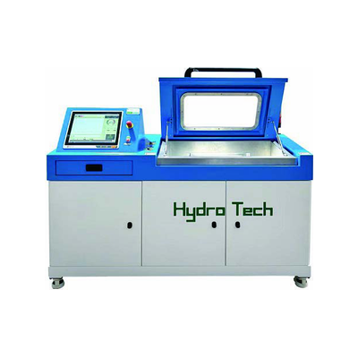
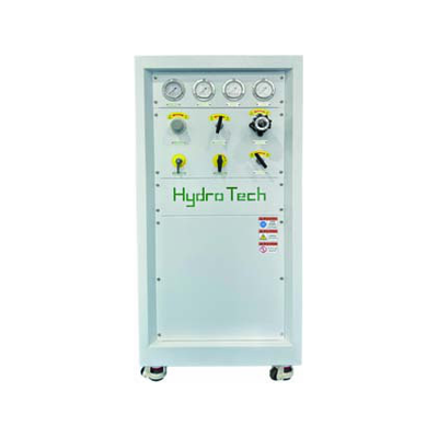
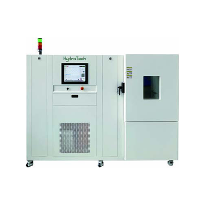
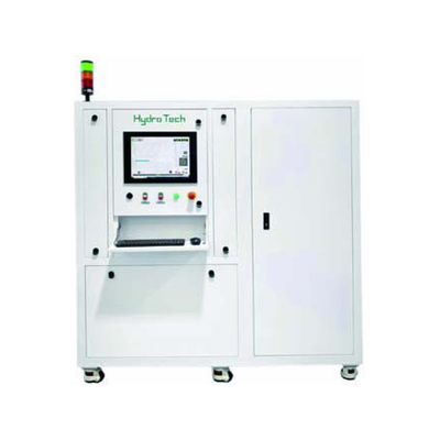
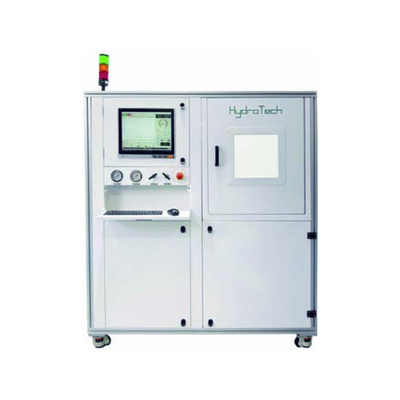
The HT-HL is a dual-channel hydraulic cycling system for the 10 – 140 bar range. Its two channels run independent pressures and frequencies simultaneously, so two different conditioning recipes can be in progress on the same bench — the usual case when a gauge line and a sensor line are being brought to stability at the same time.
Technical data
| Pressure range | 1 – 14 MPa (10 – 140 bar), extendable to 200 – 400 MPa |
|---|---|
| Test medium | Water, or ISO VG 46 anti-wear hydraulic oil |
| Pulse frequency | 0.1 – 1 Hz |
| Waveform | Triangular, sine |
| Channels | Two independent channels — separate pressure and frequency per channel |
| Drive | Plant compressed air driving a hydraulic intensifier |
| Control | Programmable pressure curve, pulse frequency and cycle count per channel |
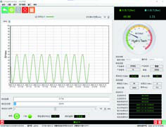
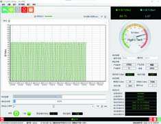
| Data | P–T curve display and recording, test data export |
| Dimensions | 2000 × 800 × 1500 mm |
What it does
- Applies repeated pressurisation to relieve the internal stresses left by forming, welding and assembly.
- Runs two recipes at once, each channel with its own pressure and frequency.
- Uses water as the medium where oil would contaminate the part or the cleanroom.
- Records both channels against time, so the conditioning history of each batch is documented.
Typical use
- Stress relief of Bourdon tubes and capsules before final calibration.
- Stabilizing pressure gauges and transmitters so that zero and span stop drifting after shipment.
- Pre-conditioning of sensors ahead of a specification test, so that the measured error is the sensor’s, not the assembly’s.
Why stress relief matters
A Bourdon tube or a welded diaphragm carries residual stress from forming and joining. Left alone, that stress relaxes slowly over the first months of service, and the reading walks. Cycling the part a few hundred times at and above its working pressure relaxes most of it before the part leaves the factory — the difference between a gauge that holds its zero and one that comes back as a complaint.



How a unit is specified
Part count, cavity volume and frequency per channel. With two channels the two loads add up on the intensifier, so the total volume displaced per cycle is what sizes the drive.
Standard and custom
The intensifier, accumulator and valve group are the standard platform. Channels, fixture stations and adapters are configured per order.