 +49 211 540747 030
 info@kuemago.com

Blog
Knowledge for better measurement decisions.
Practical insight for the questions that arise between specification and operation.
Measuring a CDU Loop: Sensors for Data Center Liquid Cooling
Liquid cooling moved the heat problem into a pipe. What follows is a measurement problem: flow, pressure and temperature at a handful of points, kept under continuous watch.
The 65-second walkthrough below runs through the same loop end to end: the CDU, the rack branches, the four measurement points, and the IO-Link layer that collects them.
Sensor solution for data center liquid cooling — flow, pressure and temperature on a CDU loop.
Why a liquid loop needs its own measurement plan
Air-cooled racks fail slowly and visibly. A fan stops, a hot spot spreads, and the room tells you. A liquid-cooled rack fails differently: the coolant is inside a closed loop, the electronics are dry, and nothing looks wrong until the flow drops, a pump loses head, or a quick-disconnect starts to weep. By the time the temperature alarm fires, the useful warning window has already closed.
That is why a CDU — the coolant distribution unit that sits between the facility water and the server racks — is instrumented rather than merely controlled. Every branch that feeds a rack carries a flow reading, the supply and return manifolds carry pressure and temperature, and the whole set is monitored continuously rather than sampled at commissioning.
The measurement points themselves are conventional. What has changed is how they are wired, and that is where IO-Link earns its place in this application.
Four measurement points on a CDU
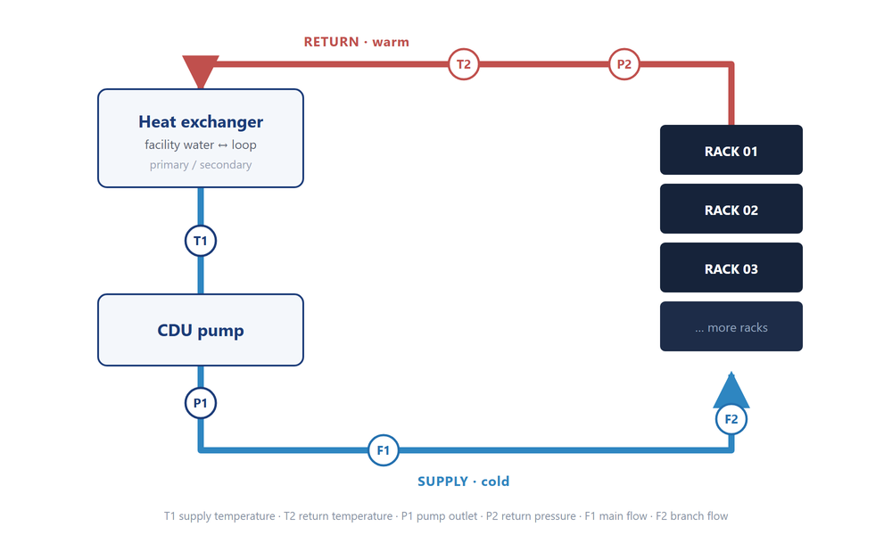
The diagram above is the whole measurement plan, and it repeats on every CDU regardless of vendor:
- Temperature on the supply and on the return — two readings whose difference is the actual cooling power delivered.
- Pressure on the pump outlet and on the return — the pair that shows whether the pump is doing its job and whether the loop is intact.
- Flow at the main loop and at branch level — the total the pump moves, and the share each rack actually receives.
Temperature: supply, return, and the difference that matters
In the system our video walks through, supply runs at 20.4 °C and return at 40.2 °C. Neither number is interesting on its own. The 19.8 K difference is the delivered cooling, and it is the number that tells an operator whether a rack is being served properly or whether the loop has quietly lost capacity.
That makes accuracy at the sensor secondary to consistency between the two sensors. Two transmitters that each read 0.3 K high cancel out in the difference; two that are each accurate to 0.1 K but disagree by 0.4 K do not. Using the same model on both lines is the simplest way to keep the pair honest.
The TBH smart IO-Link temperature sensor covers this role where the loop is already digital: the reading arrives as IO-Link process data, switching points and analog span are set over the same cable, and the display gives a fitter a local number when he is standing at the manifold. Where a Pt100 element is already installed and only the electronics are being replaced, the THH06N IO-Link temperature transmitter takes the RTD directly and offers 4–20 mA as well, so the same part can serve a digital loop now and an analog cabinet later.
Pressure: pump feedback and loop integrity
Pressure does two jobs on a CDU. On the pump outlet it is the feedback signal for pump control: 3.2 bar at the supply and 2.7 bar on the return, as shown in the video, gives the pump a target and the controller a way to notice when the duty point starts to slide. On the return it is a health signal — a falling differential across the loop means a clogged strainer, a closed valve, or a leak that is still small enough to be worth catching.
Both readings sit close to the pump and to the manifold, in a cabinet that is already crowded. A sensor that has to be opened and adjusted with a laptop is a liability there. The SEH smart pressure sensor puts measurement, switching and IO-Link communication in one housing, with a four-digit display and a housing that rotates through 300° so the reading can be faced whichever way the pipe runs. Switch points and analog endpoints are set through IO-Link, which means the commissioning engineer can configure four sensors on a manifold from one connection instead of opening each one.
Flow: the main loop and the branches
Flow is where a liquid-cooled installation differs most from an air-cooled one, because the interesting number is not the total. It is the branch.
At main-loop level, the video shows 36.0 L/min moving through the CDU. At branch level, the same system reads 12.0 L/min on a single rack feed — and that branch reading is what detects a partially seated quick-disconnect, a kinked hose, or a rack that has been added without rebalancing the manifold.
The FMV-040 IO-Link vortex flow sensor suits branch monitoring particularly well: it reports flow and temperature on a single device, so one tapping gives both the flow figure and the local coolant temperature, and the dual display shows both without a second instrument. Vortex measurement has no moving parts in the flow path, which matters in a loop that is expected to run for years without maintenance access.
At the main loop, where pipe diameter grows and the flow is higher, the alternatives are the GF-AM1 electromagnetic flow sensor for conductive coolants in a full-bore installation, or the GF-KS clamp-on ultrasonic sensor where the pipe must not be cut — useful in a retrofit where the loop is already filled and pressure-tested.
Bringing 22 signals back without 22 cables
Count the points in the monitor shown at the end of the video: twelve branch flow sensors, two main flow meters, four pressure transmitters, four temperature transmitters. Twenty-two measurement points on one CDU, and in a conventional design each one runs its own analog pair back to a PLC card.
This is the part of the installation that IO-Link changes. The field devices are collected locally, at the manifold, and one communication cable carries the whole group to the controller.
Two paths lead there, depending on what the sensors already are:
- Existing analog sensors — 4–20 mA or 0–10 V — are brought into IO-Link by a SIOL M12 analog IO-Link hub, which digitises several analog channels into one IO-Link port. This is the path for a CDU built from conventional transmitters.
- Sensors with a serial or RTD output are handled by the CIOL-2AI-SC current-input converter, the CIOL-2VI-SC voltage version, or the CIOL-PT12-SC for Pt100 elements. Each channel becomes an IO-Link process value with its own diagnostics.
The collected IO-Link lines terminate at a master mounted in or near the CDU cabinet. Three fieldbus versions cover the usual plant standards: ELPN for Profinet, ELIP for EtherNet/IP and ELCT for EtherCAT. All three are IP67 field units with an integrated industrial Ethernet switch, so several masters on one CDU can be daisy-chained instead of home-run to a cabinet.
What IO-Link actually buys in a cooling loop
The tempting argument is cable count, and cable count is real: twenty-two analog pairs become a few IO-Link lines plus one Ethernet uplink. But the operational arguments matter more in a facility that runs unattended:
Diagnostics before failure. An IO-Link device reports a broken wire, a short, or an out-of-range process value over the same cable that carries the measurement. On an analog loop, a drifting signal and a failing sensor look identical until someone walks the pipe with a meter.
Parameter recovery on replacement. A pressure sensor on a pump outlet carries a configured switch point, a damping value and a span. With parameter storage enabled on the master, a replacement device is written back to the same settings on connection. In a data hall where a failed sensor is swapped during a maintenance window, that removes the step where someone has to remember — or look up — how the old one was set.
One sensor, several values. A vortex sensor on a branch returns flow and temperature together over one port. Where the controller needs both, this removes a tapping and a device from every branch.
Digital values with no drift. There is no 4–20 mA conversion at either end, so there is no span error to calibrate out of the receiving card.
A configuration that matches the loop
For a CDU instrumented along the lines above, the parts list is short and repeats:
- Branch flow + local temperature: FMV-040 vortex sensor, one per rack feed.
- Main loop flow: GF-AM1 electromagnetic or GF-KS clamp-on ultrasonic, depending on whether the pipe can be opened.
- Supply and return pressure: SEH smart pressure sensor, two per loop.
- Supply and return temperature: TBH or THH06N, two per loop, matched as a pair.
- Signal collection: SIOL analog hub or CIOL converters at the manifold, ELPN / ELIP / ELCT master in the cabinet.
Nothing in that list is specific to liquid cooling. What is specific is the density — twenty-odd points on a single unit, in a cabinet with no room for another terminal block — and the fact that the loop is closed and unmanned. Those two conditions are what make a local IO-Link collection layer worth the change.
If you are specifying sensors for a CDU or a coolant loop, tell us the measurement points, the coolant and the pipe sizes, and we will map them to the right devices — contact our team, or start from the IO-Link solutions overview.
Products in this article
- CIOL-2AI-SC IO-Link Converter
Dual-channel 4–20mA / 0–20mA input IO-Link V1.1, Class A interface ≤12-bit resolution, 0.5% FS accuracy M12…
- CIOL-2VI-SC IO-Link Converter
IO-Link analog signal converterDual channel 0–10V inputIO-Link V1.1 Class A interface12-bit analog resolutionM12 industrial connectorsLED status…
- ELCT IO-Link Master EtherCAT
EtherCAT IO-Link master moduleEight IO-Link master channelsIntegrated Ethernet switch100Base-TX Industrial Ethernet supportM12 A-coded IO-Link portsIP67 fully…
- ELIP IO-Link Master EtherNet/IP
IO-Link master with EtherNet/IPEight IO-Link master portsIntegrated Ethernet switch100Base-TX industrial Ethernet supportClass A or Class B…
- FMV IO-Link Vortex Flow Sensor
Flow,Temperature dual switches Range: 5-40L/min NPN/PNP/push-pull optional High-resolution lPS display Cumulative flow recording function Various thread…
- PLSN Thermal Flow Sensor
Calorimetric detection principle Flow and temperature alarm function Digital LED display with mirroring Programmable via 3…
- SEH Smart Pressure Sensor
Smart IO-Link pressure sensor Large 4-digit digital display 300° rotatable housing Switching, analog, or IO-Link output…
- TBH Smart IO-Link Temerature Sensor
Smart IO-Link temperature sensor Large 4-digit digital display 300° rotatable housing Switching, analog, or IO-Link output…
- THH06N IO-Link Temperature Transmitter
PT1000 high-precision senser Range: –50 °C to +150 °C 20–4 mA analog output IO-Link interface Stainless…