Product categories
Product tags
Recently Viewed Products
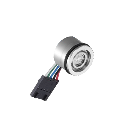
GP-310 Flush Diaphragm Ceramic Pressure Sensor
Flush diaphragm ceramic sensing element
Piezoresistive ceramic pressure transducer
Pressure range from 5 bar to 200 bar
Radiometric voltage or I2C output
Excellent corrosion and abrasion resistance
Integrated signal conditioning electronics
The GP-310 flush diaphragm ceramic pressure sensor is designed for reliable pressure measurement in applications where the process media may be corrosive or abrasive. The sensor uses a ceramic diaphragm based on the piezoresistive measurement principle, providing stable pressure sensing with high chemical resistance.
A Wheatstone bridge circuit is screen-printed onto the ceramic diaphragm and integrated within the sensor structure. When pressure is applied to the flush diaphragm surface, the mechanical deformation of the ceramic element generates a proportional electrical signal. Integrated electronics on the internal circuit board perform signal conditioning, temperature compensation, and calibration to ensure stable and accurate output.
The flush diaphragm design allows the sensor to measure pressure in applications where conventional pressure ports may be prone to clogging or contamination. Thanks to the excellent chemical resistance of Al₂O₃ ceramic material, the GP-310 is suitable for use with many aggressive media.
Typical applications include industrial process monitoring, fluid handling systems, chemical processing equipment, and measurement systems where corrosion resistance and flush pressure sensing are required.
| Items* | Alias | Min. | Typ. | Max. | Unit |
|---|---|---|---|---|---|
| Pressure Range | – | 0 | – | 1000 | kPa |
| Power Supply¹ | Vs | 4.75 | 5.0 | 5.25 | Vdc |
| Current | IO | – | 3.0 | 10.0 | mAdc |
| Min. Output | VOff | 0.44 | 0.5 | 0.56 | Vdc |
| Max. Output | VFSO | 4.44 | 4.5 | 4.56 | Vdc |
| Full Span | VFSS | 3.94 | 4 | 4.06 | Vdc |
| Accuracy² | – | – | ±1.5 | ±2 | % VFSS |
| Sensitivity | V/P | – | 2.66 | – | mV/kPa |
| Response Time (10%~90%) | tR | – | 1.0 | – | mS |
| Drift Stability³ | – | ±0.5 | – | %VFSS | |
| Power Up Time | tpon | – | – | 100 | mS |
| Weight | ~5 g (without wires) | ||||
| Diaphragm Type | Ceramic Al2O3 96.0% | ||||
| *All the parameters @ 0 to 85℃ conditions. | |||||
| 1 Within this operating voltage range, the chip output is proportional and linear. | |||||
| 2 Includes linearity error, hysteresis error, temperature error, zero temperature error and others. | |||||
| 3 Output offset of the sensor after 1000 hours of pulse pressure and temperature cycling. | |||||
| Items | Alias | Rating Value | Unit |
|---|---|---|---|
| Max. Pressure | PMAX | 3000 | kPa |
| Max. Voltage | Vmax | 20 | Vdc |
| Inverse Voltage | Vmax | -20 | Vdc |
| ESD (MIL 883, Method 3015.7.) | ±4 | kV | |
| Storage Temperature | TSTG | -50 to 150 | ℃ |
| Work Temperature | TA | -40 to 125 | ℃ |
Note:
1. Exceeding the max ratings may result in degradation of performance or damage to the sensor.
2. The max input and output currents are controlled by the impedance between output to ground and power in the actual circuit.